Rigging Physics 101 -- Redirect Pulley

  • Thread starter Thread starter rfwoody
  • Start date Start date
  • Replies Replies 66
  • Views Views 10K
attachment.php


You got it!
.
Line tension X legs of pull per point
.
For purist view,
Pulley on anchor does carry 2 X 1000 Line Tension
BUT, is 90 degree spread, so 2 X 45 degree deflection from center.
>>>>So anyway, more like 2 X 707 than 2 X 1000, pulling at angle too.
Playing that backwards, if were trying to move a log with that pulley
>> would close legs to normal for 2X power, wouldn't pull log as well with 90 degree legs of pull.
.
Pull to target tree is correct , closed legs for 2x Line Tension.
.
Don't need separate trunk positions, stay low, but evade mean taper
Tying dead end to anchor first counter-clockwise so tail serves out hold pulley.
>>and combined angle of pulley pull locks rope into tree can close angle some is better.
Take several turns on trunk, continuous direction simply crossing self 2x
So that each force functions to:
>>pinch off the other like Bag or Constrictor knots
>>acts as the other's stopper knot as well.
Do it rite and no Standing Parts deformed off of trunk anchor to purist target.
 
A>
IF my truck's hitch is somehow attached directly to the frame (vs. attached to the bumper)
-- then would that eliminate the need to attach the screw link directly to the frame for pulling?
.
B>
Usually -- but thankfully not on this job... so far (another story)
.... just drug all brush to burn pile and cut wood into ~20" lengths and more or less left in place.
good point... if yard isn't too wet/muddy

C>
..."lesson numbers of forces"(??)............What means this, please? thx.

D>
also... please, what do you call that knot in your illustration?
A>
Would look angled heavy duty beams SLANTED I'd think from frame, 120 or less spread, just like rope support, don't want flatter, want more teepee, more closed not flatter.
If is 120 not 60 spread would want cross member between points hits frame across to each other to fight cross force.
This would be like for pulling heavy equipment trailer type setup.
If set up with 2 5/16 ball to 1 1/4 hole etc probably set up. At least for your 1000# examples
But can easily load scenario more so always over build.
Some heavy pipe bumpers mite give so much leverage spread front to back for leverage strength, but I like column strength.
You've probably seen many bent out or down bumpers!
Tow hooks are generally fair, strong, placed correctly in line to frame, pull along length not across, soft arcs fading to others type builds
.
B>
With plenty of rope, anchors and pulleys can save lots of work extending mule's pull into backyards, across mushy spans etc. playing creatively to big wins. Old curved hood even for sled nose against digging in with 400# stump etc. Also, 1000# truck pull with a 2/1 pulley system reversed so pulley is on truck and not load nor anchor, can drag 500# resistance 2x as far as truck run if truck run too short. Move slow cuz moves 2x fast as truck in trade.
Similarly with pulley in tree can lift some weights on to trailer, horizontal tag line with 2 wraps limiting side rub on trailer, once plenty of lift tag line loosened to allow log to drift over trailer etc. Or other truck simply backs trailer under raised log etc.
.
C>
ABoK is knot reference, many may quote a knot by number and focus on knot, get merit badges for tying so many etc. I always and all ways thought in terms of knots shown were just displaying the real lesson of the mechanics they employed, to learn as component blocks to carry to other things and combine in modules. So numbers to me are to the force lessons , not knots. Journey more than destination mindset for sure!
.
D>
so I simply call 'my' knot as a loose splice, mind you needs TDS, Tie, Dress, Set as any other, grooming to extrude a mock splice that physically can't come out and minimal Standing Part deformity from Pure Inline, pristine strength state concept. It has been a good friend.
 
  • Thread Starter Thread Starter
  • #53
Thanks Kenny.

Yeah, thanks for the "purist" view --- ha, one knows the "purist" (pedantic/detailed?) aspect of something, one can always summarize/estimate/average from there -- you can always get from the details to a summary .... but can't get from a summary to the details.

I think everything 2 posts back makes sense -- and thanks! -- but regarding the "redirect" pulley anchored to the anchor tree.......
.... isn't that all it is? .... a mere redirect -- i.e. does not do anything for increasing/decreasing force on victim tree no matter what angle the truck is coming off it?
---- however.... 1000# of force coming off that redirect pulley at 90* means that 2x707# being exerted on pulley vs. 2x1000# --- do I understand correctly? Thanks!


On the previous post, please....

Regarding my truck........ it actually has a gooseneck hitch (ball) welded through the bed to the frame below.
my friend who I bought the truck from has hauled 8 to 9,000# loads with it.
.... would it be advisable (i.e. safe) to use this gooseneck hitch ball for all rigging pulling? ... instead of the trailer hitch?

great ideas on creative ways to use the "mule" power, sir. thanks.

Makes sense about using ABoK to learn what makes the knots tick and understand how they work.

So that knot is your own invention derived from understanding principles at least partly learned from ABoK ?
i.e. a knot that will hold without deforming the working end and is easily untied after being heavily loaded?
 
I wasn't getting how it worked from the picture...I looked again and now I see how you have it rigged...carry on Sargent...
 
I think everything 2 posts back makes sense -- and thanks! -- but regarding the "redirect" pulley anchored to the anchor tree.......
.... isn't that all it is? .... a mere redirect -- i.e. does not do anything for increasing/decreasing force on victim tree no matter what angle the truck is coming off it?
---- however.... 1000# of force coming off that redirect pulley at 90* means that 2x707# being exerted on pulley vs. 2x1000# --- do I understand correctly? Thanks!

.
On the previous post, please....
Regarding my truck........ it actually has a gooseneck hitch (ball) welded through the bed to the frame below.
my friend who I bought the truck from has hauled 8 to 9,000# loads with it.
.... would it be advisable (i.e. safe) to use this gooseneck hitch ball for all rigging pulling? ... instead of the trailer hitch?
.

So that knot is your own invention derived from understanding principles at least partly learned from ABoK ?
i.e. a knot that will hold without deforming the working end and is easily untied after being heavily loaded?


Pulleys, to non-moving points are redirects only, they do not increase power or reciprocal distance(speed).
>>Pulleys against Load divide it smaller for more power;
>>Pulleys against Input Effort, divide it smaller, for less power, but 'extrudes' more reciprocal speed(more distance in same amount of time as input)
.
If Truck pulling SOUTH, target tree EAST pulley on anchor pulls SE @ 2 X 1000 X .707 (cosine of 45, half of the span of 90)
>>purist view, for calc forces 'expressed' against anchor, nothing to do with Load(target) and Input(effort) positions.
>>pulley against tree position pulls WEST @ 2 x 1000 x 1.000 (cosine of 0 degrees deflection from pulley center line)

.

If truck is built and rated for it that is plenty of power band for 1000-3000# confident pull if not the whole band width for conservative rating.
Goose Neck like ball in bed??
But playing with power, want to gentle giant, bump and tease lightly when can, not just always bull dog.
Graceful power correctly applied, with plenty of reserve; everything constantly weighed and measured with eyes as it commences , ready to head off anything before it becomes a run-away force!


i think i came up with that knot, just call it a loose splice
Dress down, groom out long so is logical working unit, no slax.
Maintains best geometry i think, imitates strongest splices in that way.
Set so it can't escape.
How could it jam?
 
I was reading through older threads and found this and wanted to add my two sense. Kyle touched on it in the thread but the idea didn't present itself fully and completely to the OP. This would work assuming you had space for the truck to drive and in some cases it would be a no go but i think for most cases if your problem was set up like in the picture you could do it this way that im about to explain. This way is to have the rope tied off to the anchor tree and have the pulley on the victim tree. That would allow for a 2 to 1 ma roughly, it would all depend on the angles of the rope and the higher the angle up to 180 the more force you will have on the victim tree.

That works the same way when setting up a rigging system in a tree most times your better off setting up two pulley with 90 degree rope angles instead of one pulley at 180 degrees while you are rigging down limbs. With at least two pulleys properly set up in the tree you could put the wood into compression making the tree stronger and allowing more lbs to be rigged safely.

In the second page the OP once again has another drawing and for the same amount of pulleys could could make a 4 to 1 via the attached picture.

I have been there before doing the best i can for what i know and it wasnt to long ago that i didnt know much about pulleys and redirects and what kind of forces the make. I found all the information i learned from online and one of the sites i learned alot from was this site in the link. If you go to the site you can jump around with the blue highlighted words or the arrows at the top right of their page will take you through the material in order.


If you know of a better way please add to the discussion, if you know anything that might be helpful please add it. That what threads like this are about. They can people down the line to find information that can make their lifes safer and easier.
 

Attachments

  • Raising-4x1-Compound.png
    Raising-4x1-Compound.png
    71.1 KB · Views: 6
What ever happened to Woody, I wonder?

Interesting re-read.

To more clearly restate myself, it seems to me, not necessarily true and open to learning, easier for someone poorly skilled to screw up a pull with a manual, either smoking a clutch or losing tension. If you have significant gear reduction that changes things all together. When pulling trees it's important to have the machine suited to the job at hand.
Some people, maybe a lot of people want to cut until the tree falls under tension, rather than knowing what kind of hinge to cut, then pulling it over when ready. This means a long time of slipping the clutch, especially if the cutter and the puller are not in verbal contact through radios.


1483127_594494797298106_1485921497_n.jpg (640×585) (bp.blogspot.com)
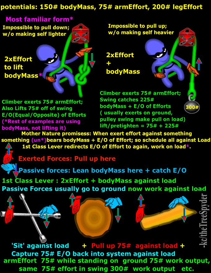
Class 1 is with the fulcrum between the load and input force, a teeter-totter.
A class 2 is with the fulcrum at one end, the load in the middle and the input-force at the other end, like a socket and racket, or wheelbarrow.
A Class 3 is with the fulcrum at the one end, the input force in the middle, and the load at the end, like lifting a shovel full of dirt with the end of the shovel stationary, and similarly a broom.
 
So the 2:1 MA on the tree is like a class 2 lever. Anchor - load/victim tree - pull.
A wedge would be either a class 2 lever if the cog is between the wedge and the hinge, or a class 3 lever if the cog is behind the wedge. Roughtly, have to take in count the force needed to fold the hinge and the wind too.
 
I read a thread that he mr woody started about him droping a tree on a house and taking electric with it. I was quite shocked when i read it but at least he wanted to learn from it. If it was me that oopsie would have never seen the light of day!
 
Last edited:
My (witnessed/self taught)take on lever trading between power and speed(distance) from the same finite volume of force:
In rigid levers, if the static pivot is between the dynamic/moving input and output parts/positions, is class_1;
only class_1 levers can reverse directions of input to output and also input/outputs work @same speed(output position_1 of 3 in imagery) where moving input/output are not next to each other, as static pivot is between.
.
When static pivot is on an end/not between input/output can take on other 2 forms/classes:
If the output/load is closest to static pivot , so the farther from pivot input concentrates into the now slower output is class_2, increasing power at co$t of distance/speed(output position_2 of 3 imagery) of inner arc.
.
Input closest to static pivot dilutes power to greater distance/speed in trade to outer arc as output(output position_3 of 3 imagery) as class_3.
.
Any conversion having a friction cost, that asserts against power, for speed/distance trades are rawly maintained. So difference in efficiency varies power input/output ratio , but distance and so speed input/output ratio ratio remains fixed when only efficiency adjusted, as weighs only against power ratio reduction.
Lever_classes_in_standard_rigid_levers%2C_as_applied_to_rope_%27rolling_levers%27.png

Will find rolling/flexible levers the same.
If static pivot is pulley position, between input/outputs, is class_1 redirect only, same speed ,power reduced by friction.
If pulley moves as output between static pivot and input increase power is class_2 at cost to distance/speed in trade.
If pulley moves as input between static pivot and output increase speed is class_3 at cost to power in traded factors to still have same product/force volume(in lossless/costless system).
.
These are for OPEN systems, things change some when CLOSE the system as in:
SaveForces_4.png

where equal and opposite of effort is expressed inside the works CLOSED, not outside to (or away from) the ground etc. in the much more common scenarios shown earlier, rather than this purposeful option.
.


This is as like watts as total volume of volts/power and amps/speed manipulations within same quantity, at cost of resistance (as like electrical friction) in force is force view. Or bottle jack narrow input piston convert to wide output piston of less motion distance output but of more power. A finite volume of force into machine to manipulate distance x power factors to same sum product volume. We choose to try to capitalize on force at co$t of distance or vice/versa from same input volume force, just as car transmission from same narrow power band of efficient car motor output etc.


Back to rigid devices, but as falling or otherwise disconnected /in air can see rules still fit from this view:
. Class_1 Pivot is most loaded point then to this view. So if stick is in air and hit an end CoG is most loaded point, as pivot I think. Unless input force lines up to CoG, then is just simple push or pull inline to CoG, not rotational to.
 
Last edited:
I knew the answer to my own question but wanted verification from others.

The diagram that I had in my post is indeed the example of a Class 2 lever system.
 
Back
Top